Draw Circle in AutoCAD

Let's start learning how to Draw AutoCAD Circles.
circles command
First you need to know how to start circle command. these are the following ways to access circle command:
Command Line: CIRCLE, C with Enter.

Menu Bar: Draw > Circle > choose option

Ribbon: Home tab > Draw panel > Circle
After starting circles command you need to choose what kind of circle you want to draw you have these options:

IS Codes for Civil Engineers

Here are the IS codes which cater to the need of civil engineering relating to Cement and Concrete. These IS codes include the Standardization in the field of all types of cement, pozzolana, testing sand, concrete, aggregates, instruments for cement and concrete testing, cement plant machinery and ferrocement concrete, reinforced concrete and pre-stressed concrete, test methods for concrete, concrete production and execution of concrete structures, performance requirements for structural concrete, non-traditional reinforcing materials for concrete structures and cement and lime.

List of Codes :- 
IS 269:1989 – Specification for ordinary Portland cement, 33 grade
IS 383:1970 – Specification for coarse and fine aggregates from natural sources for concrete
IS 455:1989 Specification for Portland slag cement
IS 456:2000 Code of practice for plain and reinforced concrete
IS 457:1957 Code Of Practice For General Construction Of Plain And Reinforced Concrete For Dams And Other Massive Structures
IS 875 (Part 1):1987 Code of Practice for Design Loads (Other Than Earthquake) For Buildings and Structures.Part 1: Dead Loads--Unit Weights of Building Materials and Stored Materials (Second Revision)
IS 875 (Part 2): Code of Practice for Design Loads (Other Than Earthquake) For Buildings and Structures.Part 2: Imposed Loads (Second Revision)
IS 875 (Part 3): Code of Practice for Design Loads (Other Than Earthquake) For Buildings and Structures.Part 3: Wind Loads (Second Revision)
IS 875 (Part 4): Code of Practice for Design Loads (Other Than Earthquake) For Buildings and Structures.Part 4: Snow Loads (Second Revision)
IS 875 (Part 5): Code of Practice for Design Loads (Other Than Earthquake) For Buildings and Structures.Part 5: Special Loads and Load Combinations (Second Revision)
IS 516:1959 Method of test for strength of concrete
IS 650:1991 Specification for standard sand for testing of cement
IS 1199:1959 Methods of sampling and analysis of concrete
IS 1343:1980 Code of practice for prestressed concrete
IS 1344:1981 Specification for calcined clay pozzolana

Draw a Lines in AutoCAD

Let’s start drawing objects in the AutoCAD. first object we start to Draw AutoCAD Lines.
You should pay attention to the command line as you work.Before starting to Draw AutoCAD Lines we should understand coordinate systems in which lines or any other geometry is drawn.
About the Coordinate System
Every geometry  drawn is placed in  the world coordinate system [WCS] or a user coordinate system [UCS]. When you create geometry, data input is given to the software in Cartesian x,y or polar coordinates [distance, angle]. You can either enter these coordinates or by clicking  point in the drawing canvas.
Types of coordinate system systems
(A)Cartesian Coordinate System
When you Draw AutoCAD Lines data inserted in the form of Cartesian x,y .The Cartesian coordinate is used to find point in space that are at a distance from a set of perpendicular axis that intersect at the origin point of the AutoCAD.
In the World coordinate system, the X axis shows the horizontal direction, the Y axis shows
the vertical direction and the origin  is located at 0,0. The Z axis moves in the positive direction directly towards , the user.
Note that for this course we will only be concerned with the X & Y points since we are working in 2D Environment. The Z coordinate will not be considered.
The given image shows a line draw from the origin with point at the coordinate 4,5.

To specify a Cartesian coordinate, type the X ,Y coordinate and press ENTER. Example:
L enter
LINE start point 0,0 Enter.
LINE next point 4,5 Enter.
A line will be drawn whose x distance is 4 units and y distance is 5 units.

Civil Engineering Books

MEGA STRUCTURE 1- Hoover Dam

Hoover dam is America's most famous landmark, completed in 1935. It was the most colossal structure in the world at that time. This great American icon was to be the largest and heaviest dam, producing the largest amount of Hydroelectric power in the world.
21000 men took part in its construction and of them 112 laid their lives to complete this megastructure. Though its not the superior dam today but still most famous, iconic and greatest dam ever built. Situated in Mojave desert, 30 Km south-east of Las Vegas. Built on Colorado River at Black Canyon, the construction site was extremely difficult. The risks involved were huge and the consequences could have been catastrophic, if the dam failed.
Hoover Dam is 221 m high, 201 meters thick and 3.4 million cubic meters of concrete has been used in it.


Why Hoover Dam was Constructed?

Colorado, worlds one of the most powerful and unpredictable rivers, would break its banks in every spring and flood the area. The Government instructed the Bureau of Reclamation to come up with a solution and they decided to build world's largest dam. The site chosen for the megastructure Hoover Dam was Black Canyon. It is an 800 ft high deep gorge through which the river flowed. The spot, Black canyon is in the middle of the desert, so there was no infrastructure, no labors, no transportation and the weather too was harsh.
Frank Crow, was the Chief Engineer of Hoover Dam and was assigned the job to get it completed in the span from 1931 - 1935. The construction of Hoover took 7 years at a cost of $ 125 million. Nowadays this amount is about 788 million pounds. If the dam was not completed in the given time it would have cost the contractors $ 3000 / day in financial penalties.

First Start of AutoCAD

While Starting AutoCAD, we have to follow some preliminary settings or steps before start to working in the AutoCAD. Before starting to work in the AutoCAD we have to do some work like opening up new file, defining the units to work in AutoCAD, controlling the work space. We will see step by step what are the primary steps to follow before Starting AutoCAD.
(1) First step [opening new file]: when we Starting AutoCAD, by default new page is already open with a default template named as [ACAD.dwt]. You can also open a new file by using shortcut [ctrl+n] or by selecting new menu from the Application Menu or new file from the Quick Access Bar.
Let’s try short cut [CTRL+N] 
When we press shortcut [CTRL+N] this window appears


when this window appears select the default template and click open new window will appear with blank black screen with ribbon. same will happen with other methods.


AutoCAD 2014 Introduction

Hello! I like to tell you Introduction to autocad 2014 interface . AutoCAD is around for 30 yrs and is  standard software tool for drafting and drawing. Engineer uses autocad in varies discipline of engineering and professions. In this blog we will learn more about AutoCAD. Starting with Introduction to AutoCAD 2014 Interface, then we will move further in coming blogs. You will learn more with practice step by step.
Now lets start with Introduction to AutoCAD 2014 Interface.
As you open the AutoCAD application by double clicking on it you will see a window of AutoCAD called the AutoCAD Interface. which will look like this:


Now i will tell you more about Introduction to AutoCAD Interface.
1) Application Menu: The red icon on the top left corner of interface is called Application menu. which holds the all menus necessary for accessing the files in AutoCAD. always remember to click once double clicking will end your session. Application Menu looks like  :


2)Quick Access Bar: this bar is on the right side of the application menu icon on top of AutoCAD 2014 Interface. In this bar, icons which are frequently used. like New, Open, Save, Save As etc.  quick access bar looks like


3)Ribbon: Ribbon is strip which is the  GUI interface for the commands so that user can access the command graphically.  it lies just below the quick access bar .It has two part two part tabs and panel.to hide the ribbon you ca either use [ctrl+0] or type a command[Ribbonclose +enter] which looks like:


4)Information Bar: Information bar gives you the information of the drawing currently you are working in.

Uniform Loads on Simply Supported Beams

A simply supported beam is the most simple arrangement of the structure. The beam is supported at each end, and the load is distributed along its length. A simply supported beam cannot have any transnational displacements at its support points, but no restriction is placed on rotations at the supports.

Fig:1 Formulas for Design of Simply Supported Beam having Uniformly Distributed Load are shown at the right

Fig:2 Shear Force & Bending Moment Diagram for Uniformly Distributed Load on Simply Supported Beam


Figure 2Figure 1
Shear Force & Bending Moment Diagram for Uniformly Distributed Load on Simply Supported BeamShear Force & Bending Moment Diagram for Uniformly Distributed Load on Simply Supported Beam

Fig:3 Formulas for Design of Simply Supported Beam having Uniformly Distributed Load at its mid span

Fig:4 SFD and BMD for Simply Supported at midspan UDL carrying Beam

Figure 4Figure 3
Shear Force & Bending Moment Diagram for Uniformly Distributed Load on Simply Supported BeamShear Force & Bending Moment Diagram for Uniformly Distributed Load on Simply Supported Beam


Civil Engineering Final Year Projects

Earthquake Related Projects
1.      Earthquake vibration control using modified frame-shear wall
2.     Advanced Earthquake Resistant Techniques
3.     Seismic isolation devices
4.     Energy dissipation devices for seismic design.
5.     Reservoir induced seismcity
6.     Failure of foundation due to earthquake

Surveying & Levelling
1.      Advance Technology in Surveying
2.     Development Of Remote Monitoring System For Civil Engineering

Engineering Materials
1.      Smart materials
2.     Basalt rock fibre (brf)
3.     Cellular Lightweight Concrete
4.     Mineral admixtures for high performance concrete
5.     Glass fiber reinforced concrete
6.     Geosynthetics
7.     Bamboo as a building material
8.     Silica fume concrete
9.     Fly-ash concrete pavement
10.  Non-destructive testing of concrete

Building Construction
1.      Causes Prevention and Repair of Cracks In Building
2.     Rehabilitation techniques.
3.     Stability of high rise buildings.
4.     Corrosion Mechanism, Prevention & Repair Measures of RCC Structure
5.     Analysis for seismic retrofitting of buildings
6.     Collapse of World Trade Center
7.     Advance construction techniques
8.     The rain roof water-harvesting system
9.     Formwork types & design
10.  Rectification of building tilt
11.   Space hotel
12.  Retrofitting using frp laminates
13.  Green buildings
14.  Passive solar energy buildings
15.  Zero energy buildings
16.  Impact of lightening on building and remedial measures
17.  Laminated flooring


Earthquake Engineering

Now a days Earthquake Engineering is the most needed and essential part to save many lives from Earthquakes comes in many counties. There a lot of effects of Earthquake can be seen in Nepal and its belonging countries. 

Definition of Earthquake Engineering:
An earthquake is a sudden slipping or movement of a portion of the Earth's crust or plates, caused by a sudden release of stresses. Earthquake epicenters are usually less than 25 miles below the Earth's surface and are accompanied and followed by a series of vibrations.


What causes earthquakes and where do earthquakes happen

The earth has four major layers: The inner core, outer core, mantle and crust. The crust and the top of the mantle make up a thin layer on the surface of earth. But this layer is not a single cover, it is made up of many pieces like jigsaw covering the surface of the earth. These keep slowly moving around each other, slide past one another and bump into each other. These puzzle pieces are called tectonic plates, and the edges of the plates are called the plate boundaries. The plate boundaries are made up of many faults, and most of the earthquakes around the world occur on these faults. Since the edges of the plates are rough, they get stuck while the rest of the plate keeps moving. Finally, when the plate has moved far enough, the edges unstick on one of the faults and there is an earthquake.

Types of earthquakes

Most earthquakes in the world occur along the boundaries of the tectonic plates and are called Inter-plate Earthquakes. A number of earthquakes also occur within the plate itself away from the plate boundaries, called Intra-plate Earthquakes.

How are earthquakes recorded

Earthquakes are recorded by instrument called seismographs. The recording they made, is called a seismogram. The seismo gram consists of two parts, a base and a weight, to held it firmly in the ground. When an earthquake causes the ground to shake, the base of the seismograph shakes too, but the hanging weight does not. Instead the spring or string that it is hanging from absorbs all the movement. Thus the difference between the moving and immovable part is recorded.


Tremie Method: Under Water Concreting


Tremie method is the most acceptable method of concreting under water.

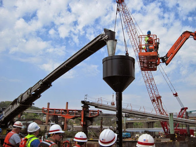
In this method a tremie pipe is inserted in the water up to the point where concrete is going to be placed. Generally the diameter of a tremie pipe varies from 20 cm to 30 cm. Depending upon the depth of concreting under water we can add more tremie pipe by coupling it with one another.
Before inserting the tremie pipe into the water, the bottom end of the tremie pipe must be closed with a plug or thick polythene sheet or other suitable material.
After tremie pipe reaches at the desired depth, a funnel is fitted to the top end of the tremie pipe, to facilitate pouring of concrete.
Then concrete having a very high slump of about 150 mm to 200 mm is poured into the funnel, until the whole length of tremie pipe is filled up with concrete.
Then the tremie pipe is lifted up and given a slight jerk by a winch & pulley arrangement. Due to application of jerk and weight of the concrete inside the pipe, the bottom plug fall and the concrete gets discharged.

HOW HOT & COLD WEATHER CAN AFFECT CONCRETE?


Effect of hot and cold weather on concrete
Concrete is not recommended to be placed at a temperature above 400C and below 50C without proper precaution as laid down in IS: 7861 (Part-1 or part-2 as the case may be).
IS:7861 part-1 deals with hot weather concreting and Part-2 deals with cold weather concreting.

Hot Weather Concreting

Special problems are encountered in the preparation, placement and curing of concrete in hot weather. High temperatures result in rapid hydration of cement, increased evaporation of-mixing water, greater mixing water demand, and large volume changes resulting in cracks. The problems of hot weather on concrete are further aggravated by a number of factors, such as use of rapid-hardening cements, handling of larger batches of concrete, etc.
Any operation of concreting done at atmospheric temperature above 400C may be put under hot weather concreting. In the absence of special precautions as laid down under IS: 7861 (Part-1), the effect of hot weather may be as follows:

A) Accelerated Setting

A higher temperature of fresh concrete results in a more rapid hydration of cement and leads to reduced workability/ accelerated setting. This reduces the handling time of concrete.

B) Reduction in Strength

Concrete mixed, placed and cured at higher temperature normally develops higher early strength than concrete produced and cured at normal temperature but at 28 days or later the strength are generally lower.

C) Increased Tendency to Crack

Rapid evaporation may cause plastic shrinkage and cracking and subsequent cooling of hardened concrete would introduce tensile stresses.

D) Rapid Evaporation of Water During Curing Period

It is difficult to retain moisture for hydration and maintain reasonably uniform temperature conditions during the curing period.

E) Difficulty in Control of Air Content in Air-Entrained Concrete

It is more difficult to control air content in air-entrained concrete. This adds to the difficulty of controlling workability. For a given amount of air-entraining agent, hot concrete will entrain less air than concrete at normal temperatures.
In order to avoid harmful effect of hot weather concreting IS: 7861 (Pt.1) recommends that temperature of ingredients should be controlled so that the temperature of produced concrete is lower. Mixing water has the greatest effect on lowering of temperature of concrete. The use of chilled water/ flaked ice in mixing produces adequate reduction in concrete temperature.
In order to control the temperature of concrete and to avoid adverse effect of hot weather, it is desirable to limit the maximum temperature of concrete as 350C to keep margin for increase in temperature during transit.
Click Read More for Cold weather Concreting

Precast Concrete Piles – Advantages & Disadvantages

Precast concrete piles are cast, cured and stored in a yard before they are installed in the field mostly by driving.

Advantages of Precast Concrete Piles
  1. Reinforcement used in the pile is not liable to change its place or get disturbed
  1. The defects in pile can be easily identified after the removal of forms, and these defects (such as presence of cavity or hole) can be repaired before driving the pile.
  1. The cost of manufacturing will be less, as a large number of piles are manufactured at a time.
  1. Precast concrete piles can be driven under water. If the subsoil water contains more sulphates, the concrete of cast in situ piles would not set. Thus precast concrete piles have added advantage in such a circumstance.
  1. Precast concrete piles are highly resistant to biological and chemical actions of the sub soil.
  1. Better quality control can be implemented as compared to bored cast in situ piles.
  1. These piles can be constructed in various cross-sectional shapes such as circular, octagonal or square.

GASIFICATION – THE ULTIMATE SOLUTION TO THE WORLD’S ENERGY NEEDS AND ENVIRONMENTAL PROBLEMS


The combustion of fossil fuels is taking a tremendous toll on the earth’s atmosphere and consequently on the environment. Global warming and pollution threaten the very existence of life on our planet. Moreover, most fossil fuel resources are expected to become depleted within the next few decades and thus prices have already skyrocketed. Governments, scientists and even industrialists themselves have long realized that fossil fuels will not remain economically and environmentally feasible and are thus looking towards alternative sources of energy such as nuclear, solar, wind energy and so on. One of the most practical and efficient methods of energy production is gasification – a process which involves conversion of organic or carbonaceous materials into hydrogen, carbon dioxide and carbon mono oxide.

GasificationThere are 7 billion people on this earth and they produce tones of organic waste every day. This waste is can be used to solve the energy needs of the world. When organic material decomposes in nature, it releases greenhouse gases into the air and the remnants serve to nourish the soil. The process of gasification is similar to what happens in nature, except for the fact that it takes place much faster. Organic waste is used to create gases which are burned to produce energy and the remaining ash is used as a fertilizer. Even when the gases are derived from fossil-based carbonaceous substances, the resulting gases are much more efficient than the original fuel as they can be burned at higher temperatures and even in fuel cells.

INTRODUCTION OF CIVIL ENGINEERING

There are many people who would like to work in the engineering field as the civil engineer in recent years. What would the civil engineer do? You would find some ideas here.

In the past, the field of civil engineering covered many areas. For example, there would be coverage over the use of chemicals in the field. There would also be more details about the mechanical sides. But you would probably find that things have changed in recent decades. More and more specific fields are separated from the civil engineering field. They became the chemical engineering and other specific fields. The traditional civil engineer therefore now covers fields like design and building constructions. There would be, in other words, a narrower definition of the work that the present civil engineers would do.

Softwares For Civil Engineers

AutoCAD:-  

AutoCAD is a semi parametric software tool that is used for drafting and 2D Design mostly. This software is invented by Autodesk Inc. in earlier 1982, now they published AutoCad 2015 their 29th version that is AutoCAD 2015. This is used for making layouts of the residential or commercial buildings. It is world famous software and used by all industries.

Staad Pro :- 

STADD PRO v8i is purchased by Bentley in 2005, today in market they launched Staad Pro v8i Select Series 5. It a geometry based Analysis Software, all industries used this at higher end. All Types of buildings are analyse with different kinds of loads acting on it suck as Seismic Load, Wind Load, Vehicle Load in Bridges. This software contains 70 Countries Codes from worldwide, and 30 Indian Codes Suck as IS456, IS 800, IS 1893 etc. 


Google SketchUP is the best ever software for work in 3D drawings and Rendering. One of the main from its feature is that its licence is at very low cost and easily google sketchup available. For interior and exterior design of buildings this software is compatible in all directions. Mostly this software is used for walkthrough purpose. It means we can see the virtual images of our building before construct It is also called Rendering. This Software has a one more feature that is Geo Location Access, it means we can upload our building in google earth in any area, it can show the real environment of the surrounding where you placed the building.