Retaining Walls – Types, Design, Stability

Retaining walls may be defined as a wall built to resist the pressure of liquid, earth filling, sand, or other granular material filled behind it after it is built. It is commonly required in the construction of hill roads, masonry dams, abutments and wingwalls of bridges and so on. Depending upon the site conditions, type of material to be retained and the height of the wall to be constructed, retaining wall may be built in dry Stone masonry, stone masonry, brick masonry, plain cement concrete and reinforced cement concrete.
Types of Retaining Walls:
Some of the types of Retaining Walls are,
  1. Gravity Retaining walls
  2. Cantilever Walls
  3. Counterfort walls
  4. Buttress Walls

Dry Stone Retaining Walls:
This is the simplest form of retaining wall. The stability of such walls depends upon the arrangement of stones in the wall and the friction between the individual stones. The stones used in the wall should be of large size and roughly hammer-dressed so as to ensure maximum bedding area. The wall should have a minimum top width of 60 cm. and the front face should have a batter varying from 1 in 4 to 1 in 3. The batter of I in 4 is adopted for walls lesser than 4.5 m in height. In principle, the height of dry stone masonry wall should be restricted to 6 m. For walls above 4.5 m in height, the upper 4.5 m of the walls is usually built of dry rubble stone masonry and the portion below this height is built with mortar.
The stones used in the wall construction are laid at right angle to the face baller. A proper bond is maintained and the front and the rear faces of the wall are nicely bonded with the hearting. The filling immediately behind the wall should consist of stone chips gravel or similar granular material and not earth. 75 to 100 mm. square weep-holes should be provided in the wall at 2m c/c vertically and horizontally to drain off the water from the filling behind. The wall has been shown in figure 943 on page (252).
Dry Stone Pitching or Revetment:
It is generally provided to protect the slopping face of an earthen cutting or embankment from erosion. Stones used, should be perfectly sound and roughly cut to fit in the shape of the pitching. In case of channels and dams, pitching should be carried at least 90 cm. above the high flood level and to ensure its stability, the toe should be prevented from slipping by suitable construction. The slopes of embankment should not be steeper than 1:1, a slope of 1½ : 1 being usually adopted. The thickness of pitching varies from 30 cm. to 75 cm. Selected stones are tightly hand packed and all the interstices are filled up with smaller pieces of stone and wedged up tight. Every stone in pitching is laid flat and no projecting stones are allowed.
Concrete Curing Methods – Curing of Concrete

What is Curing:
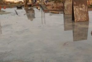
It may be defined as the operation of keeping a freshly placed concrete moist during a specified period after its finishing to ensure complete hydration of cement particles or other cementing material for obtaining a properly hardened concrete.
The concrete starts attaining its strength immediately after its setting is completed, and it continues to gain strength thereafter along with time. About 90% of concrete strength is attained in the first 28 days and its value is generally known ad design strength. Development of the concrete strength is primarily due to hydration of cement which takes place only in the presence of water. It is therefore necessary that water in the capillaries in prevented from evaporating. For proper hydration of cement particles in a freshly placed and compacted concrete, a proper environment of humidity and temperature needs be maintained. This process is called ‘curing’
Curing of Concrete

Compaction Factor Test – Workability of Concrete

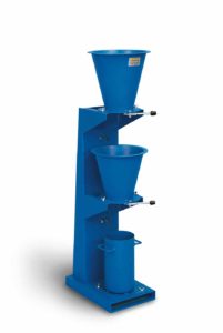
Compaction Factor Test is designed in such a way that it can be used only in laboratory but in some cases, it can be used for field concrete tests. The compacting factor test has been developed at the Road Research Laboratory in United Kingdom. This test is one of the most accurate test performed in order to determine the workability of concrete.
The apparatus of compaction factor test is shown below.
COMPACTING FACTOR TEST APPARATUS

Mega Structure 6 - Akashi Kaikyo Bridge

Akashi Kaikyō Bridge, also called “Pearl Bridge”, is located in Japan and considered as Japan’s finest engineering feat. Akashi Kaikyō Bridge is the world’s longest suspension bridge in the world with a length of 3911 meters (12,831 ft). The Akashi Kaikyō Bridge serves as a link between the city of Kobe and Iwaya by crossing the Akashi strait. The construction was finished in a span of 12 years which actually begin in the year 1986 and completed in the year 1998. The bridge plays an important role in providing three routes across the inland sea.

Top Super Expressways of India

India, a developing country has world’s third largest road network but when we talk about expressways, we can hardly name a few like Mumbai-Pune Expressway and Delhi-Gurgaon Expressway. So we decided to tell you about some of the other expressways in India.
Here is the list of India’s top Super Expressways
1) Ahmedabad Vadodara Expressway
Ahmedabad Vadodara Expressway is 95 km long and joins Ahmedabad and Baroda in Gujarat. It is also referred as National Expressway 1. This expressway was opened to public in 2004 and was constructed under the Golden Quadrilateral Project by NHAI.
2) Mumbai-Pune Expressway
Mumbai-Pune Expressway (official name is the Yashwantrao Chavan Expressway) is 93 km long and is considered as one of the best expressways in India. It is India’s first six lane high speed expressway and was made by Maharashtra State Road Development Corporation (MSRDC) at a staggering cost of Rs 1,630 crore (US$363.49 million). It was opened to public in April 2002

3) Jaipur-Kishangarh Expressway
Jaipur-Kishangarh Expressway is 90km long and it connects Jaipur with Kishangarh. It was constructed under the Golden Quadrilateral National Highways Development Project and its cost was USD 154 million. More than 20,000 vehicles pass from this highway everyday.

4) Allahabad Bypass
Allahabad Bypass covers a distance of 86 km and is one of the most remarkable achievements of the Golden Quadrilateral project. It connects India’s four main metropolians New Delhi, Kolkata, Mumbai and Chennai.

Mega Structure 5 - World One

World One is a supertall residential skyscraper under construction in Mumbai, India. It is located in Lower ParelSouth Mumbai on the 7.1-hectare (17.5-acre) site of the defunct Shrinivas Mill. The site also houses two other towers—World View and World Crest. World One is being built at an estimated cost of over US$320 million. Construction began in 2011, and is expected to be completed in 2018. Once complete, World One will be the tallest building in India, and the tallest residential tower in the world.

Lodha’s World One will bring India’s name in the list of some of the world re-known engineering projects as it will be the tallest residential tower in the world.
Project Details and Costing
Location- Upper Worli, Mumbai, Maharashtra, India.
Site Area – 17.5 acre
Land Acquired from Srinivas Cotton Mills By Lodha Group for Rs 250 crore (US$40 million)
Project Cost – Rs 20 billion (US$320 million)
Expected Revenue from Sales – Rs 50 billion (US$800 million)

Architect 
Pei Cobb Freed & Partners are the architects for World One. This company has more than 200 awards for design excellence which include 24 AIA National Honor Awards.
Structural Engineer
Leslie E. Robertson Associates (LERA) are the ones doing structure designs for this project. They have vast experience in designing tall buildings as their earlier projects included the Shanghai World Financial Center, Bitexco Financial Tower, World Trade Center in New York.

Mega Structure 4 - Chenani – Nashri Tunnel

Prime Minister Narendra Modi on Sunday dedicated Asia's longest bi-directional road tunnel on the Jammu-Srinagar National Highway to the nation. The Chenani-Nashri tunnel will cut down travel time between Jammu and Srinagar by two hours.

Modi was accompanied by Road Transport and Highways and Shipping Minister Nitin Gadkari and Minister of State for PMO and MP from Kathua-Udhampur constituency, Jitendra Singh.

The Rs 2,519-crore all-weather tunnel is equipped with world-class safety features and has been built in a record four years on the hilly terrain of Jammu and Kashmir, Road Transport and Highways Minister Nitin Gadkari had said earlier.

"This state-of-the-art 10.89-km tunnel between Udhampur and Ramban in Jammu and Kashmir, an engineering marvel on the most difficult terrain of the Himalayas, was built in a record four years," the minister had said.

Mixing and Batching of Mortar And Concrete Ingredients

ABSTRACT:
A concrete plant, also known as batch plant is device that combines various ingredients to form concrete. In general, it is a process of combining all ingredients of concrete as per the mix design. Batching and mixing are extremely important parts of mortar and concrete manufactures they influence properties of concrete both in plastic as well as in hardened stages. Also, it is one of the important processes, which is to be done to obtain a quality concrete. Many processes are carried out in various parts of the world with many changes and different equipment. There are various types of batching and mixing equipment and methods that is to say from manual to most sophisticated computerized batching and mixing. Mechanization improves quality of batching and mixing, its speed and thereby can most often result in economy.There are number of factors which are to be considered while doing the process which are discussed in this paper. Moreover, the machinery, which is to be required while making concrete or for batching process and discharging and unloading of the mixture, are also discussed in brief.

1.0 INTRODUCTION:
Concrete is the most widely used construction material in the world. This material is not going to be easily replaced by any other material on account of its economical as well as the technical advantage.This material is generally produced at the site in our country and therefore needs to be carefully supervised and controlled in order that it performs the way it is technically expected to perform.
Concrete is made from raw materials such as cement, natural and manufactured aggregates, water and at times concrete additives (chemicals). It is worth noting that cement and aggregates are manufactured or obtained from natural solid stone, which is quarried, crushed, screened and processed to give the required physical and chemical properties.
This paper covers the batching and mixing process of concrete manufacture. The processes of batching and mixing of concrete or mortar materials are very similar to preparations of a dish in cookery as per a recipe wherein various ingredients depending on their individual properties have to be mixed in correct proportions to give the required flavour and taste.

Plastic Cracking of Concrete

1.0 INTRODUCTION:
Cracking is one of the major issues in concrete. Since concrete has various physical and chemical properties it is prone to cracking. Its elimination is not possible totally but it can be restricted or reduced to a certain extent. Mostly, cracking goes on a microscopic scale and does not appear visibly as a fault. If the cracking goes on a macroscopic scale it can result in loss of strength, stability and durability. It can also cause decrease in sound insulation and overall efficiency besides affects aesthetics to a greater extent.
The main causes of cracking are as follows:
  • Ageing – Carbonation
  • Foundation problems
  • Weathering Actions
  • Improper or modified use of the structure
  • Poor maintenance
  • Progressive loading
  • Deficiencies in design
  • Poor quality of concrete material
  • Improper concrete mix
  • Movement of concrete arising from physical properties
  • Poor workmanship and negligence
  • Over troweling and impermeable formwork
  • Reduced continuity of the structural member
  • Defects and errors in construction practices
  • Improper structural repairs or modification
  • Chemical attacks by Chlorides and Sulphates
  • Differential thermal stress – Heat of hydration of cement

Since, prevention is better than cure it is always preferable to prevent cracking to a certain or a possible extent than to think of repairs in the future due to various reasons. One of the frequent occurrences of cracking of concrete is due to plastic shrinkage of plastic settlement. This paper deals with various aspect of these types of cracking.
2.0 OCCURRENCE OF PLASTIC CRACKING:
Both plastic shrinkage and plastic settlement cracks occur within a few minutes or hours of concrete placing and finishing. They occur when concrete is still in plastic state and has not fully hardened. They can be seen as early as 10 minutes from the time of placing and finishing to as late as 3 hours after placing.
The plastic cracks are of two types:
1. Plastic settlement Cracks
2. Plastic shrinkage Cracks

The Effect of Bagasse Ash and Rubber Tyre Waste in Concrete

Abstract
The utilization of industrial and agricultural waste produced by industrial process has been the focus on waste reduction research for economical, environmental and technical reasons. SCBA is a fibrous waste product of the sugar refining industry, along with ethanol vapour. Bagasse ash mainly contains aluminium ion and silica. The use of SCBA as a pozzolonic material for producing high strength concrete. OPC is partially replaced with finely SCBA. At present the disposal of waste tyre is becoming a major waste management problem in the world. In this project, the bagasse ash has been chemically and physically characterized and partially replaced in the ratio of 0%, 5%, 15% and 25% by weight of cement in concrete. The mix proportion for M30 grade concrete was derived. Rubber tyre waste has been used as coarse aggregate with replacement of conventional coarse aggregate and it is taken as constant of 10%.
INTRODUCTION 
Ordinary Portland cement is the most extensively used construction material in the world. Portland cement is the conventional building material that actually is responsible for about 5%-8% of global CO2 emissions. This environmental problem will most likely be increased due to exponential demand of Portland cement. Today we are focusing on ways of utilizing either industrial or agricultural waste, as a source of raw materials for industry. This waste, utilization would not only be economical, but may also result in foreign exchange earnings and environmental pollution control. Several researchers and even the Portland cement industry are investigating alternatives to produce green building materials. Industrial wastes, such as blast furnace slag, fly ash and silica fume are being used as supplementary cement replacement materials. Agro wastes such as rice husk ash, wheat straw ash, hazel nutshell and sugarcane bagasse ash are used as pozzolanic materials for the development of concrete. Currently, there has been an attempt to utilize the large amount of bagasse ash, the residue from an in-line sugar industry and the bagasse-biomass fuel in electric generation industry. When this waste is burned under controlled conditions, it also gives ash having amorphous silica, which has pozzolanic properties. Solid waste is concerned with waste tyres, has become a problem of interest because of its non-biodegradable nature. Tyre rubber wastes represent a major environmental problem of increasing significance. Most of the waste tyre rubbers are used as a fuel in many of the industries such as thermal power plant, cement kilns and brick kilns etc. this material can also be used for non load-bearing purposes such as noise reduction barriers. Investigations about rubber waste concrete show that concrete performance is very dependent on the waste aggregates. Further investigations are needed to clarify for instance which are the characteristics that maximize concrete performance.

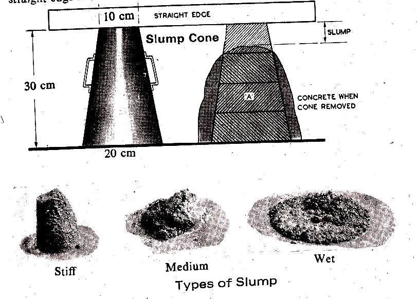
Slump Cone Test and its Advantages and Limitations

Although, the slump cone test is not entirely satisfactory since it gives widely varying results and also does not give a true measure of workability but it is of value in the field as a control test and is useful in comparing the consistence of successive batches of concrete made with the same ingredients and is one of the simplest tests to carry out. Provided no change is made in the aggregate or its grading, slump cone tests will indicate whether correct water and cement contents are being maintained. For a given slump and aggregate grading, the water required for unit volume of concrete is constant irrespective of the change of cement content. The amount of slump depends not only on the amount of water in the mix but also on the nature of the aggregate ; rounded stones give a greater slump than angular stones for the same mixture.
Slump Cone Test

Engineering Drawing Scales

There is a wide variation in sizes for engineering objects. Some are very large (eg. Aero planes, rockets, etc) Some are vey small ( wrist watch, MEMs components)
There is a need to reduce or enlarge while drawing the objects on paper. Some objects can be drawn to their actual size. The proportion by which the drawing of aan object is enlarged or reduced is called the scale of the drawing.
Definition
A scale is defined as the ratio of the linear dimensions of the object as  represented in a drawing to the actual dimensions of the same.
·        Drawings drawn with the same size as the objects are called full sized drawing.
·        It is not convenient, always, to draw drawings of the object to its actual size. e.g. Buildings,
·        Heavy machines, Bridges, Watches, Electronic devices etc.
·        Hence scales are used to prepare drawing at
o   Full size
o   Reduced size 
o   Enlarged size

BIS Recommended Scales are shown in table 1.
Intermediate scales can be used in exceptional cases where recommended scales can not be applied for functional reasons.