Mega Structure 2 - Chesapeake Bay Bridge Tunnel

For over 50 years, the Chesapeake Bay Bridge-Tunnel has captured worldwide attention as a modern engineering wonder and an important East Coast travel convenience. Crossing over and under open waters where the Chesapeake Bay meets the Atlantic Ocean, the Bridge-Tunnel provides a direct link between Southeastern Virginia and the Delmarva Peninsula (Delaware plus the Eastern Shore counties in Maryland and Virginia), and cuts 95 miles from the journey between Virginia Beach and points north of Wilmington, Delaware. Following its opening on April 15, 1964, the Bridge-Tunnel was selected "One of the Seven Engineering Wonders of the Modern World" in a worldwide competition that included more than one hundred major projects. In addition, in 1965, it was distinguished as "The Outstanding Civil Engineering Achievement" by the American Society of Civil Engineers. To date, over 116 million commercial and passenger vehicles have crossed the Bridge-Tunnel. In order to meet future traffic demands and provide for a safer crossing, construction of a parallel crossing project began in summer 1995, and opened to four-lane traffic on April 19, 1999. No less challenging than construction of the original span, this project once again drew focus to a remarkable achievement in engineering and construction.

From the early 1930's to 1954, a private corporation managed scheduled ferry service between Virginia's Eastern Shore and the Norfolk/Virginia Beach area. With the number of ships (including the number of passengers and vehicles they transported) increasing steadily, the Virginia General Assembly stepped in to create the Chesapeake Bay Ferry District and the Chesapeake Bay Ferry Commission as the governing body of the District; subsequently the Chesapeake Bay Bridge and Tunnel District and Commission. 
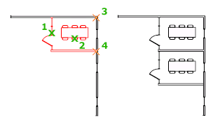
Copy in AutoCAD

This command is Applicable to AutoCAD_2016, AutoCAD_Architecture_2016, AutoCAD_Civil 3D_2016, AutoCAD_Electrical_2016, AutoCAD MEP_2016, AutoCAD Map 3D _2016, AutoCAD Mechanical_2016, AutoCAD P&ID_2016, AutoCAD Plant 3D_2016, AutoCAD Structural Detailing_2016, and AutoCAD Utility Design_2016.
AutoCAD COPY Command Copies the object at a specified distance in a specified given direction.
 look for this icon in Modify toolbar or 


CO Enter in Command Line
With the [COPYMODE] system variable, you may control whether to create multiple number of copies of the object automatically.
AutoCAD COPY Command COPY Command AutoCAD COPY Command GUID 7A9EC2F4 4552 491C BED9 EA8C1CED533F
The following are asked in the command line after initiating the Command :
Select object to copy:  select the specified object to copy and then press [Enter]
Specify basepoint or <Displacement/mOde/Multiple> : Specify a basepoint i.e. base point is the point considered for the reference vector displacement  or enter any one of these options Displacement or mode or Multiple.
Specify 2nd point or [Array] [use 1st point as displacement]: Specify a 2nd point or displacement or enter the available option.

Displacement_

Specify a relative distances and directions using coordinate or cross hair .
The two point you specified defines a vector that indicate how far from original the copied object are placed and in which directions.
If you press [Enter] at the Specified Second Point , the 1st point is interpreted as relative to X,Y,Z displacements. For example, if you specify 3,4 for the basepoint and press [Enter]at the next step, the object is copied 2 unit in the direction and 3 unit in the Ydirection from their previous location.

Draft Settings in AutoCAD (3D Object Snap)

3-D Object_Snap setting controls the dynamic object_snap settings for 3-D object.

With dynamic 3-D Object_Snap setting, also called Osnap setting, you may signify the snap point at the specified position on the objects. When more than one option are choosen, the choosen snap mode is applied to give a point closer to_center of  aperture_box. Press TAB to jump on the option.
List of available Option
3-D Object_Snap [On/off]
It Turn 3-D Object_Snap on and off. The 3-D Object_Snap selected under 3D Object_Snap Mode is active while Object_Snap is on. [3DOSMODE system variable]
Object_Snap Mode
Lists the 3D Object_Snap mode.
Vertex_
It Snap to closer vertex of a 3-D objects.


Drafting Settings in AutoCAD (Dynamic Input)


Drafting Settings (Dynamic Input) command is Applicable to AutoCAD_2016, AutoCAD_Architecture_2016, AutoCAD_Civil 3D_2016, AutoCAD_Electrical_2016, AutoCAD MEP_2016, AutoCAD Map 3D _2016, AutoCAD Mechanical_2016, AutoCAD P&ID_2016, AutoCAD Plant 3D_2016, AutoCAD Structural Detailing_2016, and AutoCAD Utility Design_2016.

List of Available Option in Drafting Settings (Dynamic Input) 
Enable Pointer_Input
Turn on pointer_input. When pointer_input and dimensional_input are turned on, dimensional_input supersede pointer_input when available. [DYNMODE system variable]
Pointer_Input
Display locations of cross hair as coordinates value in a tool-tip near the cross hair. When command prompt you for points, you may enter coordinates value in the tool-tip instead of in Command_window.
Preview Area_
Show examples of pointer inputs.
Settings_
Display Pointer_Input Setting box.
Enable Dimension_Input
Turn on dimensional_input. Dimensional_input not available for some command that prompts for 2nd point. [DYNMODE system variable]

Scale Command in AutoCAD

AutoCAD Scale Command
AutoCAD Scale Command used to Enlarge or reduce the size of the specified object, while keep proportions of the object same after scaling of the object.
Access Method of stretch command

Find this icon from the following options:


Tool bar: Drafting tool set >>Scale
 Menu bar:  Modify >> Scale.
Shortcut: Select object to scale. Rightclick in the drawing canvas and click Scale.
Command method: [SC Enter]
To do scale objects, specify base-point and scale-factor. The base-point act as centre of scaling operations and remain fixed. A scale-factor greater than one enlarge objects. Scale-factor less than shrink objects.

Steps involved during Scale Command
The following steps are to be followed:
Start Scale Command by [SC Enter] or the methods discussed above.
Select object: Use objects selection methods and press Enter when you are done.
Specify base-point: Specify point which will be fixed.
The base-point you specified identify point that remain in same location as selected object changes size (and thus moves away from fixed base-point).
Note: When user use Scale Command with annotative object, the positions or locations of objects is scaled relative to base-point of scale operations, but sizes of the objects is not change.

Rotate Command in AutoCAD

utoCAD Rotate Command
AutoCAD Rotate Command used to rotate object or geometry around a fixed point called base-point.
AutoCAD Rotate Command rotate command AutoCAD Rotate Command 110
Find this icon in the modify toolbar or form the ribbon.
User will be to rotate object around a base point to the absolute angles.

The following steps are to be completed after activating the AutoCAD Rotate Command.

Select_object
This option need you to use object selection methods and press [Enter] when you are done.
Specify_base-point
Specify the desired point about which the object is rotated which means the selected point will be fixed.
Specify the rotation angle:
This option let you Enter angle values or specify coordinate point, or enter [c] for copy , or enter [r] for reference.
  • Rotation_Angle:Determine how much objects rotate around a base-point. The axis of rotations pass through the specific base-point and parallel to axes of the current User Coordinate System.
  • Copy:Create copies of selected object for rotations.
  • Reference:Rotate object from specified angles to new, absolute angles. When you rotates a view-port objects, the border of the view-ports remains parallel to the edge of drawing canvas.
You may rotate object in drawings around a specified base-point.
To determine the angles of rotations, you may enter angle values, drag using cross-hair, or specify reference angles to aligns to absolute angles.

Move Command in AutoCAD

AutoCAD Move Command helps user to Move the object to a defined displacements in a defined directions.
AutoCAD Move Command move command AutoCAD Move Command 19
Find this icon from the Modify Toolbar to activate the command.

AutoCAD Move command Uses coordinate, grid snap, object snap, and other tool to moves object with high precision.
The following instructions will be asked in the command line after activating the command from the modify tool bar or [M enter] in the command line.

Select_object
This options used to Specify which object to be moved.
Base_point
This option help us to Specify the start_point for the object to be moved. Important to be careful during base point declaration because this point decides the displacement distance.
2nd_point
In this option  combinations with the 1st point, specify a vector that indicate how long, and in which directions, the selected object are to be moved.
If user press [Enter] to accept the Use of the 1st point as displacement, the 1st point is taken as relative X,Y,Z displacements. For example, if you specifies 4,5 for the base_point and press [Enter] at the next , the object move 4 unit in the X-directions and 5 unit in the Y-directions from the original positions.

Draft Settings in AutoCAD (Object Snap)

This setting Control the  running point snapping on the geometric object.snapping of point like endpoint, mid point, center, quadrant etc.

Note:- 3D Object_Snap  is not available in AutoCAD_LT.
With Object_Snap settings, which is also called Osnap, you may point out  snap_point at an exact point on  objects. When more  options selected at a time, the specified snap mode are applied to give points closer to center of  aperture_box.hold TABkey to move through given option.
List of available Option
Object_Snap [On/off]
With  object snaps active,objects snap selects under Objects Snap Mode are active while signifying point on object when the command is in action. [OSMODE system_variable].
Object Snap Tracking_[On/off]
With object snaps tracking, crosshair may tracks along alignment path based on current objects snap mode when signifying point in command.(AUTOSNAP system_variable).

Object_Snap Mode

Lists object snaps that you can turn on as running object snaps.

Draft Settings in AutoCAD (Polar Tracking)

This setting Controls the Auto Angle Tracking settings.

Note:-3D Object Snap is not available inDrafting setting in AutoCAD_LT.
Lists of available Option
Polar Tracking [on/off] setting:
It applies a restriction for crosshair movement to given  angles. [AUTOSNAP system variable]
Polar Tracking Angle Settings:
It Set restriction for alignment of polar angle for polar tracking. [POLARANG system variable]  
[Increment Angle:
It Set polar angle increments  use to display polar_tracking alignment paths. [POLARANG system variable]
You may specify angle of your choice , or pick commonly used angle from given list.
Additional_Angles:
Make  addition of angles in  lists given for polar_tracking. [POLARMODE and POLARAD DANG system variables]
Note:- Additional_angles are absolute, not incremental_in nature.

Draft Settings in AutoCAD (Snap and Grid)

snap and grid in AutoCAD.
Snap: It is AutoCAD tool help you to reach specific point or location with accuracy and easily when you want to pick any point. With help of this you can easily jump from one point to another equal point and draw angular lines.
Grid: Grid is the continuous array of rectangular area on AutoCAD GUI which helps you to give a general idea about the drawn objects.

You can control snap and grid setting in drafting settings Dialog box. To enter in drafting settings dialog box you need DS enter. There are following points are displayed in the drafting setting dialog box:
  1.    Snap On dialog box
You can turn Snap mode on or off by clicking Snap Mode on the status bar, by pressing F9, or by      using the SNAPMODE system variable.
  1.   Snap Spacing
Control on a non- visible, rectangular grid of snap location that restrict pointer movement to specific X and Y interval.
  • Snap X Spacing tab
Specify the snap gaping along X direction. The value must be a non-negative real number.
  • Snap Y Spacing tab
Specify the snap gaping along Y direction. The value must be a non-negative real number.
  • Equal X and Y Spacing tab
To makes the X and Y spacing with same value snapping and grid snapping. The intervals in snap spacing and grid snapping may be different.

Draw Ellipse in AutoCAD

AutoCAD Ellipse Command.
AutoCAD Ellipse Command Access.
1)Command Line: Ellipse or  EL Enter.

2)Ribbon: Home tab >> Draw panel >>Ellipse.

To Create an AutoCAD Ellipse or an AutoCAD elliptical arc.you should know about Ellipse is that
The 1st two point of AutoCAD Ellipse define the position and length of first(major) axis. The 3rd point determine the distance between  center of AutoCAD Ellipse and  End point of second (minor)axis.

To Create an AutoCAD Ellipse:
Start with [El Enter].

Axis Endpoint
Defines the first(major) axis by clicking two endpoints or by providing start point and length of axis in specific direction. The given axis may define  the major or  minor axis of AutoCAD Ellipse.

Draw Polygon in AutoCAD

Rectangle and other closed counter loops are type of polygon i.e. closed counters with more than or equal to three sides. The AutoCAD Polygon command provide a much faster method of drawing a polygon (all side of polygon and angle subtended by them at center are same or equal ).
The given step guide  how to work with  the AutoCAD Polygon command:-
First: Click AutoCAD Polygon command from the drop-down Draw panel of Ribbon in home tab , or type [POL Enter].

AutoCAD starts the Polygon command and asks you enter the number of sides for the polygon.like this
Enter number of sides <4>:

Second: Type the number of side of the polygon to be drawn and then Enter.
Your polygon make a polygon have sides ranging from 3 to 1,024 .
AutoCAD ask you to mention the center point of the polygon.like this
[Specify center of polygon] or [Edge]:

Or
You can use the Edge option to draw  Polygon  by mentioning length of  side of the polygon
Third: click the center point on drawing canvas or insert coordinates(x,y).
AutoCAD asks you to mention whether the  Polygon is inscribed circle whose radius you specify in fifth Step  (the vertex of the  Polygon will be on the boundary or circumference  of the circle) or circumscribed circle (the sides of AutoCAD Polygon will be tangent to circle).
Command line shows this:
Enter an option [Inscribed in circle/Circumscribed about circle] <I>:


Draw Arcs in AutoCAD

AutoCAD Arcs Command Access.
1)Command Line: ARC or  A Enter.
2)Ribbon: Home tab > Draw panel > Arc.


First: 3 Points ARC method circle
This command creates an AutoCAD Arcs using three points on drawing canvas. Using the default method for creating an arc, you specify a start point, a second point, and an end point. The arc radius and center point are calculated based on the position of the three consecutive points you specify.
For 3 points AutoCAD Arcs, you have to select  [Draw panel>>Arc>>3 Points] from the ribbon then pick a point on Drawing canvas for the 1st point of your arc. Then  Specify Next point of arc  which means you need to select second point of the ARC. After clicking  point on drawing canvas, specify last or end point for arc. then the arc will be created.

Draw Rectangle in AutoCAD

Use the Rectangle command to create AutoCAD rectangular object. A single poly line object is created with the command. The easiest method for creating a rectangle is to specify the first corner, then the opposite corner. Other options for creating the rectangle include the Area, Dimension, and Rotation options.
Command Access
Command Line: RECTANGLE OR REC .

Ribbon: Home tab > Draw panel > Rectangle.

when the rectangle command started we will see command line ask you following options.

Sub-Command Options available before and after the first corner point selected :